This is the original Brutus system from Lonnie McAllister of Bacliff, TX
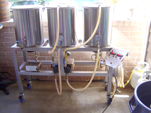
Meet Brutus! Brutus “Ten” is an example of pure will power. This brewery was built from 2″ X 2″ Stainless steel square box tubing, all fabricated on our small apartment patio. This was quite an endeavor, and one I was not prepared to tackle. A new welding machine, many supplies and many, very many nights of hard work all paid off in the end. Here we have a great 11 gallon brewery, automated HLT and fully automatic RIMS. This system is controlled by two LOVE temp switches, each controlling a stainless ASCO valve plumbed into the gas system. This allows full automated control of the HLT and MT.
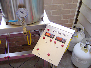
The control panelTwo LOVE temperature switches, main power switch, individual switches for each temp switch and their respective ASCO valves as well as switches for each March pump |
|
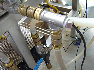
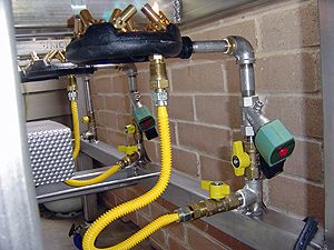
Gas
Notice the gas beam that is pressurized to about .4 psi. The welded tee fitting and all. The pilot branch is always pressurized at the 1/4 turn valve. The burner branch at the top of the tee is pressurized to the ASCO valve. When the LOVE switch opens the ASCO valve, gas flows to the burner that I have preset with its1/4 turn valve. Of course with the pilot always lit, it fires up and only shuts off when the temp switch tells the ASCO valve to. |
|
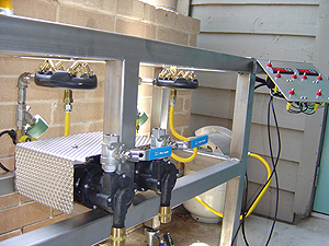
Pumps
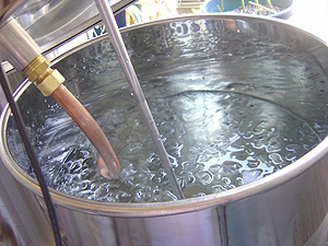
Two march pumps with a decorative stainless steel shroud. Center, and mounted low keeps them right where the action is needed. I have always had great luck orienting the outlets in the up position. Fly sparging on this single tier requires two pumps to keep things flowing. |
|
Mash Tun
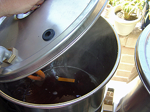
I have tried just about everything in the mash tun. Bazookas, copper tubing… Several iterations of false bottoms. This has worked best. The mash clears very fast during recirculation, and I am getting great efficiencies pulling sugars from every part of the mash. This system employs a direct-fire (very low heat RIMS) mash tun, slowly recirculating the mash from the bottom back to the top of the tun while the ASCO valve controls the amount of heat applied to the bottom of the tun. |
 |
Temperature Control
Temp readings for the recirculating mash are taken at the outflow of the mash tun. This has proven to be the best method. The output is closest to the heat source. If the direct heat source is set at 150 degrees, the whole mash can never go over this temp. As the 150 degree recirculating wort is returned to the top of the mash, the mash as a whole will catch up to the output temperature. This is how I control the mash. It is very accurate. |
 |
|
The HLT is set to recirculate to itself as well, recirculating the 170 degree sparge water back to itself using pump 2… I set the flow rates of each pot to match each other as best as I can. |
 |
The spargeThis is a BIG pain. All I have to do after getting the flow rates matched in the MT and the HLT is move the pot lid from the HLT to the MT, and the pot lid from the MT to the boil kettle… Hard work indeed |
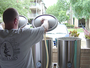 |
Fly sparge whirlygigSince the beginning of my brewing days I have been a fly sparger at heart. I have moved back to the fly sparge method. In the Mash lid I have mounted a Williams Brewing fly sparger. This is one piece of pro stainless whirlygig! I have never been so pleased at my efficiency. |
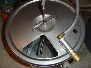 |
Return lid
The tube in the return lid is simply a means to return the wort, the cooling water, the sparge water, whatever to it’s respective pot that I set it on. A 90 degree fitting attached to a curved piece of copper that when the lid is installed, the copper tube is actually touching the side of the pot on the inside. This can be used to return the hot wort from the mash to the kettle as I do during the sparge! (Hot side aerators I join you!!) or cooling, whirlpooling… whatever you can dream. There is no need to automate the boil kettle burner burner. As in any system, this phase should be left to instinct. |
 |
Chilling
The Therminator I use in an unusual manner, as I do everything else! I have the kettle flowing to the Therminator, then to the pump inlet, and back to the kettle through the pump outlet. I run it this way for the whole cooling cycle. It returns to the kettle. The wort is returned and sets up a great whirlpool as well. I just let it run like this. Notice the frost on the cooling HLT tank at 35 degrees with 4ea 7lb bags of ice, and the kettle! On the chilling side of the Therminator I first knock the heat out using a garden hose. This will bring the wort temp down to below 140 degrees in 3 minutes. This is my goal, to get below the DMS production threshold as fast as I can. Chilling is a real feat in Texas. Ground water is hot. To supplement chilling further, I switch the hoses to the HLT, where I pump freezing ice water through the Therminator. This will knock the whole batch down to 65 in under 20 minutes. The HLT has now become a chill water tank. Using the second pump, I just pump the ice water through the Therminator (chilling side) and back to the top of the tank in the same manner as I am pumping the hot wort through the Therminator and back to the kettle. It is really a hands off system at this point. Both the cooling wort, and the chill water are recirculating within their pots, whirlpooling, lots of action, not dead spots. When done, I know that the whole batch is at 65, not just part of it. |
 |


Share Post