
Richard Trevino explains how to turn an ordinary side-by-side refrigerator into a beastly, beer monster fridge. The fridge functions as a kegerator on the left side and a fermentation chamber on the right, and he even has enough room for a few six packs! Remarkable indeed.
(Take note of the abbreviations legend at the bottom)
Tools
- Angle grinder, dremell or cut off tool
- Phillips and flat head screw driver
- Wire cutters
- Wire nuts or soldering iron
- Electrical tape
- Drill and drill bits
Parts
- Love TSS2 controller
- 2 temperature probes
- 120 VAC PC fan
- Extra wire
- Draft beer faucets
- Beer shanks
- CO2 line
- Beverage Line
- Louvered dryer vent
 To make good consistent beers, I knew that I would need consistent variables which I could duplicate each time I made a particular beer. I built myself a Brutus system, very similar to Lonnie Mac’s but I still did not have a way to maintain my fermentation temperatures, so I decided on building a fermentation chamber. My first idea was to take an old fridge and install a Ranco or Love controller so that I could easily maintain my desired temperatures; but then that meant that I would need another refrigerator for kegging. Two refrigerators take up a lot of space use a lot of energy, so I began to think about using a side-by-side refrigerator to use as a kegerator and as a fermentation chamber.
While doing some searching on the internet I saw a post by Forbien11 on homebrewtalk.com where he had accomplished just what I wanted to do. The positive thing with the way it was done was that the adaptive defrost function stayed in place. This would prevent me from having to manually defrost the unit when ice built up. The downside (not necessarily a negative thing) was that he was not able to reach temperatures in the low 30s on both sides of the refrigerator due to the factory damper system in the refrigerator’s side. He also had not installed any faucets into the system so he has to open the freezer side each time he wanted to pour a beer.
My idea was to use the basic outline of what Forbien11 had done, but eliminate the factory damper controls, install taps in the doors, install a 120 VAC PC fan and a Louvered vent to prevent air movement between the two zones when the system was not calling for circulation.
After finding a Frigidaire side-by-side on Craigslist for $80 I ordered a Love TSS2 and two temperature probes from Dwyer Instruments, as well as three Perlick faucets and shanks, and all of the necessary CO2 and beer lines. Once all of the parts arrived I removed the factory icemaker and auger assembly from the freezer compartment, these are easily removed after unscrewing a few Phillips head screws and unplugging the wiring harness in the back of the freezer.
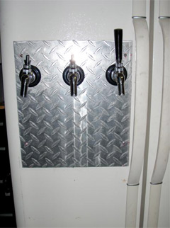
Next I removed all of the controls from the freezer door by simply popping off the outside trim of the control panel and then removing the Phillips head screws around the perimeter. Then came the ice delivery door and the water spigot, these are only held in by two Phillips screws on the outside of the door. I then took an angle grinder and cut out what was remaining in the door, this left a hole about 10″ x 12″ in the freezer door but provided plenty of room for the shanks to go into the freezer without protruding past the inside door frame.
 I then took a piece of aluminum diamond plate that I had lying around and cut it to size to cover up the large opening, drilled out the spots for the three shanks and then using stainless screws secured it to the door.
Next I took a piece of plastic and placed it on the inside of the freezer door and secured it with some duct tape and filled the void with expanding foam to insulate the area. This plastic was removed about two days later and slowly over the next couple of days the rest of the foam dried. I would recommend using something rigid instead of plastic like I did, the foam bulged out and I had to go back and shave it down to make it a flat surface.
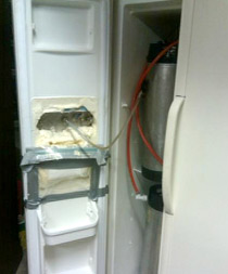
The CO2 lines for the kegerator portion were simply run through the hole that previously held the factory water line. On the inside of the freezer I installed a CO2 manifold with three lines for the three serving kegs.
Next, inside the refrigerator side of the side by side I accessed the factory refrigeration controls by removing the Phillips screws on the underside of the trim running the width of the ceiling and along the upper left wall. Under the front trim you will find the refrigerator light and the two thermostats, one for the freezer and the other for the refrigerator. Inside of the trim running along the upper left of the refrigerator you will find the adaptive defrost board and at the very back the damper control. There are a lot of wires and it can be very confusing but don’t get discouraged. Remove both of the thermostats and the damper controls, these will no longer be used.
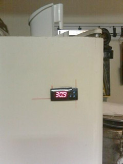
I decided that I wanted to see the Love controller, so I decided that I would install it in the refrigerator door. To do this, I took a dremel and made the cut in the outside sheet metal, then trimmed the interior plastic so that the controller could slide right in.
An alternate location for installation would be in the right side wall; or you could easily route the wires up through the ceiling and mount the controller in a box on top of the refrigerator.
 In order to install the 120 VAC PC fan I began by removing the back cover of the freezer to access the factory cut out where the air is exchanged between the freezer and refrigerator. The PC fan I purchased was about 6” x 6” and the factory hole is only about 2” square, so I placed the fan in the upper right corner of the freezer and traced the outline of the fan on the wall between the two sides. I then took a box cutter and cut the shape out and removing the skin from the freezer wall, being very careful to not cut all the way through to the refrigerator side. After the general shape was cut out of the freezer side I removed the Styrofoam insulation from the middle wall and slid the fan right into place. On the refrigerator side the hole is just a little smaller, preventing the fan from passing all the way through the wall. The PC fan wires pass through the wall from the freezer (SP1) side to the refrigerator side (SP2). Lastly, I installed reinstalled the rear cover in the freezer compartment.
Inside the refrigerator side you should have a bigger opening where the PC fan is now able to blow greater volumes of air from the freezer into the refrigerator. At this point a louvered dryer vent can be installed to help prevent the unwanted exchange of air between the two compartments. At first I did not install the vent and did not have any problems but I decided to just add the vent in case I ever want to turn off the right side (SP2) and not have any cold air exchange, thus raising the temperature in SP2.
In order to power the controller you will need to cut the black and light blue wires going to the defrost board. A wire will get spliced into the black so you will have three black wires, one will go to #5 on the controller and the other black goes to the original black on the defrost board. Two wires will be spliced into the light blue, one will go to #4 on the controller, 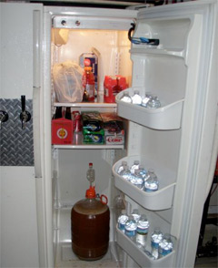 one will go to the 120 VAC PC Fan and the other will go back to the defrost board. At this point, check to make sure the controller is working by plug the refrigerator back in and you should see the controller should turn on and display an error, don’t worry its only because the temperature probes are not plugged in.
Now it’s time to hook up the compressor, PC fan and temperature probes. The black wire that was connected to #5 will need a jumper to #7 (this will power the compressor) and #10 (this will power the pc fan). Cut the orange and white wire going to the defrost board and splice in a wire going from the defrost board to #8 on the controller, when the controller calls for cooling this will single the defrost board to switch the compressor on. The last part of the factory wiring that needs to be addressed are the purple and white wires going from the defrost board to the damper controls which is no longer needed and the green grounding wire on the main wire harness, both are no longer needed and can be capped off.
In order for the PC fan to work, a wire will need to be run from the #11 on the controller to the other wire on the PC fan that has not yet been connected. When the refrigerator side (SP2) calls for cooling, this will turn the fan on and pull the cold air from the freezer side (SP1) into the right side (SP2).
Connect the two temperature probes to the controller, run the probe connected to #1 and #2 into the freezer side (this is SP1) and the probe connected to #2 and #3 stays on the right side (this is SP2).
Now that everything is connected plug the refrigerator in, the controller should boot up and after a few second the temperature of SP1 will be displayed. Hold the SET button down for a few seconds to get into the programming mode and enter the following values:
Legend
SP1 – Temp for freezer
SP2 – Temp for Fridge
r0 – ind
r8 – ON2
c0 – This is the length of time between allowing the switch to come on. I tested the unit with a value of 0 so that the controller would switch on every time there was a call for cooling. Once I was sure that it worked properly I changed it to 15 minutes.
c1 – dir
c2 – dir
P5 – 2
These two control how much temperature swing you want before the unit calls for the function to be switched on.
R1 – Temperature differential for SP1 (I set mine to 2, so if SP1 is 2 degrees above the set point and c0 has been exceeded then cooling will be switched on)
R2 – Temperature differential for SP2 (Mine is also set to 2)
At this point the only things to do are dress up all of the wires and plug it in. I have had my unit running for several months now and can say that it is working just fine. Good luck and better brewing to you.
If you’ve got a pimped out system of your own share it in on the AHA Forum under the Pimp My System category. Don’t be bashful; show off your creativity! Who knows, you could be the next star of Pimp my System…
The AHA Forum is communications central for the homebrewing community. Draw upon the collective knowledge of homebrewers around the world to get your questions answered. Help out your fellow homebrewers with their questions.


Share Post