I started brewing on my first RIMS system in about 1994, having read the article in Zymurgy by Rodney Morris on how to build a RIMS system. I had an electronics engineer at work help me wire wrap the temperature controller circuit. Since then, the system has gone through 4 major upgrades, all of which can be seen at my website http://hbd.org/hollen. There are many more pictures and much more detail on this site.
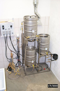
My current system is made from 3 half barrel kegs (all obtained legally), a stainless steel stand which I fabricated and welded myself, a heater chamber containing two low density elements, a surplus magnetically coupled pump and an electronics control box, also fabricated by myself. This system is housed in my dedicated brewery room in my workshop. There is a 200 CFM exhaust system above the brewing stand, a 4”x36” floor drain and a laundry sink with an additional dedicated bottle washer. There is also a hose with hot and cold water coming out of the wall next to the laundry sink.
 Heater Chamber
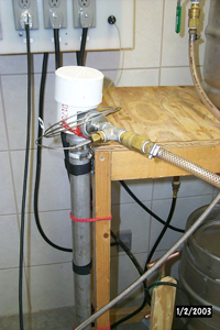
The heater chamber is a length of 1-½” stainless steel pipe with T fittings on each end. It contains two Grainger part #2E768 low density, nickel alloy heater elements. These elements are designed to run at 6000 watts on 240 volts, but I run them at 120 volts, thereby cutting the watt output by 4, down to 1500 watts each. Each element is about 22” long and folded over on itself twice, resulting in a watt density of about 15 watts per square inch. A watt density of any higher than this can lead to scorching of the wort.
The heater elements are protected on each end of the chamber with 4” PVC pipe fitting “hats” so that no one can touch the electrical connections. All of the electrical cords plug into dedicated GFCI outlets (2 – 20 amp circuits, one for each heater element).
The heater chamber is designed so that it can be completely disassembled and cleaned thoroughly after every brew. This is necessary, as I found out the hard way, because some grain bills will leave a residue on the heater elements that if left on and wet will rot and create a horrible stench.
The thermocouple sensor that hooks up to the PID temperature controller is on the output side of the heater chamber. The reason for this is that with the setpoint being monitored at the output, the wort which contains the majority of the enzymes in the mash will never overheat. Yes, there is a small lag in the main mash getting to the same temperature as the circulating wort, but there is never any problem of denaturing the enzymes in the wort by overheating.
 Pump & Couplings & Hoses
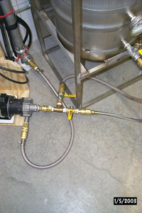
I was very fortunate to get a few surplus March pumps many years ago. They are magnetically coupled, with a 1/8 hp motor and a stainless steel impeller housing. These pumps are worth about $1500 each, but I obtained them for $40 each used. Yes, 1/8hp is way larger than necessary, but I use a speed control to slow down the pump during recirculation.
Every fitting and hose on the system is connected with Hansen brass hydraulic quick disconnect couplings. This makes it very easy to disassemble and clean after every brewing session. The pump inlet has a manifold with two valves so that the input can easily be switched from mashtun to hot liquor tank. The hoses that are input from the mashtun and hot liquor tank are semi-rigid Teflon with SS overbraid. This very hefty material prevents any collapse from occurring under heat and suction. All hoses on the output side of the pump are food grade vinyl with the internal braiding.
 Control Box
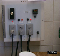
I fabricated the control box from plywood and scrap nylon sheet. There are input and output grills on bottom and top, and a small 110V muffin fan to bring air through the box while in use. Two 10 gauge cords bring power into the box. One cord powers one heater element and the pump, and the other cord powers the other heater element and the PID temperature controller. Each cord is on a dedicated 20amp GFCI circuit because each of the heater elements draws 11amps.
The pump speed is controlled via a commercial ceiling fan motor speed controller. The PID temperature controller is an Omega CNI16D22-EI, which is a 1/16 DIN controller with two displays, two SSR outputs and an Ethernet interface with embedded web server. The PID cannot switch the 11 amp draw of the heater elements, so it instead triggers two 25 amp solid state relays which do the actual switching on and off of the heaters. There are two red indicator lights in the front panel of the cabinet which are wired in parallel with the heater elements so that it is easy to see when they are on or off. The pump control also has an indicator light.
 Mashtun
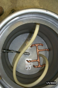
The mashtun is a converted half barrel keg with a SABCO full width false bottom. The pickup tube is fabricated from ½” SS tubing and Swagelok fittings. There is a T fitting and two valves on the outlet of the mashtun so that the output can easily go either back to the pump or down into the boil kettle. The mashtun is at the highest level of the system so that the head for the pump is as much as possible. The return to the mashtun from the heater chamber is through the wall of the keg at the top. This allows the pump to have a very high head feeding it by gravity, since a magnetic pump is NOT self-priming. The returning wort goes through a silicone rubber hose and down into a 6 outlet copper return manifold so that the returning wort will not create channels in the grain bed.
Boil Kettle & Hot Liquor Tank
The boil kettle and hot liquor tank are both half barrel converted kegs. The hot liquor tank has no false bottom, and the boil kettle has an ABT false bottom that looks like an upside down pie tin with holes in it. The liquid pickups on both kettle and HLT were fabricated out of ½” SS tubing and Swagelok fittings. All of the sanitary welding on the mashtun, HLT and kettle was done by Jeff’s Stainless Solutions in San Diego, CA. I am capable of doing structural welding on the stand with my MIG welder, but doing the sanitary welding correctly required both a TIG welder and years of experience welding SS, which I do not possess.
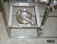 Stand & Burners
I fabricated the stand myself from ½” SS square tubing and angle. The mashtun sits at the highest point and gravity feeds into the kettle. The kettle gravity feeds down through a coiled counterflow chiller and into a fermenter (I ferment in corny kegs). The hot liquor tank is at the lowest level and all sparge water is pumped up from there to the mashtun. The burners are fed through a dedicated 15psi propane line which is hooked up to the 250 gallon propane tank which we use for our house heating. No running out of propane in the middle of a brew for me! Between the 15psi propane supply and the burner manifold is a pressure regulator. The manifold is ½” black iron pipe with three burners attached, one for each of mashtun, kettle and HLT. The burners on the HLT and kettle are 55k BTU burners with a 4” ring of flames. However, the mashtun burner is only a 30k BTU 10” ring burner. All are fitted with SS wind screens from MoreBeer, which is also where I got the burners. The reason I have a burner at all on the mashtun is that sometimes I have a huge grain bill that would cause the upward ramp time of the mash to be too slow even with the two heater elements. In those rare instances, I turn the burner on under the mashtun as well while ramping from protein to sacchrification rest and then on up to mashout. This also saved a brew on the day when my PID controller decided to die on me just as I was coming up to mash-in temp.


Share Post