Good fermentation and happy yeast often comes down to temperature. Too cold and the yeast goes dormant, too hot and they indulge in an orgy of fermentation that’s difficult to fix. You could submerge it in cold water and periodically add ice to cool it down, or throw a warm blanket around it and hope for the best. However, neither of these two methods, or any other difficult to control method is less than ideal.
Cooling System Inspiration & Function
Dan Curtis, who joined the AHA in 2012, agreed. When he purchased his conical fermenter a few years ago, he wanted to control his beer but not swallow the extra cost for a cooling unit.
After a year of unhappy fermentation, he modified his 14-gallon MoreBeer! conical fermenter for a Peltier cooler and heater system with a dual stage temperature controller, which he mentions can chill his beer to 33°F (0.5°C) with an ambient temperature of 67°F (19.4°C).
Below are the instructions that can be used for a 14-gallon conical fermenter, in conjunction with the Peltier cooler fermentation system instructions provided by Rob Swanson. Curtis used Swanson’s instructions as a springboard for his build and although his instructions aren’t step-by-step, they should provide some insight into how the build was completed.
Materials

- 14-gallon conical fermenter
- 12 ft of 22ga wire
- 12 ft 18ga wire
- Wire cutters
- 500w Computer PSU
- Control Products dual Stage Controller TC9102D
- Thermal Grease: Buy 10 and get 30 free in order to cover the four Peltiers and the fermenter side of the aluminum blocks. These tubes are small. Make sure you use plenty of thermal grease.
- 4x CPU Heatsinks with fan
- Breeze Make-A-Clamp Kit SS
- ¾” black foam type insulation
- 4x Peltier chips (you can find less expensive chips on eBay if you’re willing to wait)
- 2x Aluminum plates 10″ (T6511)
Instructions
Step 1: First you need to mill the aluminum, which if you don’t know an experienced machinist, can be difficult to find. I suggest finding someone who has a Computerized Numerical Control (CNC) machine, which use computer controls to cut different materials before you begin this project, so this step is done correctly. This could take a while, and will cost in the $100 range or less.
The fit between the conical and the metal heat sink needs to be precise. The aluminum needs to be milled to fit the curvature of the conical. After you have your plates milled, make sure to have the parts lapped or sanded down to ensure quality contact with the Peltiers and fermenters. The first time I constructed this system, I didn’t do this step and noticed a significant difference once I did.
Step 2: You need to override the jumper on your PSU to cause it to start without a motherboard. See here for instructions (switch is optional). Next, cut the black molex connector from the CPU cable of the PSU. You’ll have four black-yellow 12v rails for the four Peltier chips.
Step 3: Clean every contact surface with rubbing alcohol to ensure a clean surface.
Step 4: With your CPU heatsinks with fan, remove the fan and swamp the fan direction. This helps to remove heat from the Peltiers. Next, identify the cold side of your Peltier and place the cold side down on the heatsink.

Note: It is important to have the heatsinks tightly snug with the Peltier chips between them and the aluminum blocks. I used #6-32 1/2″ screws and shimmed them up if they were too long with #6 flat washers.
Step 5: Apply the thermal grease to fill invisible thermal gaps. Spread between the aluminum block and the Peltier, as well as the Peltier and the CPU cooler.

Step 6: I used 22 gauge wiring to connect the heatsink fans and used 18ga wiring to connect the Peltier chips all to the PSU’s CPU wiring. I then used 3/8″ plastic protective wire wrap to run my wiring. Make sure to test the connections over a 20 to 40 minute period.
 Step 7: For my setup, I didn’t install a power supply on the fermenter, but installed it on the wall with a receptacle to plug in the power supply for cooling and the heating pad for heating. The 120V output for the controller was wired to the receptacles on the line side to supply power to the proper receptacle. I also installed a switch in the power supply to the controller so I could turn it on/off with the flick of a switch.
Step 8: I used a Breeze Make-A-Clamp Kit SS system to mount the aluminum blocks to the fermenter. I used two pieces to mount them. One above and one below the heat sink. Apply a thin layer of thermal grease to fill in the gaps of the plates.
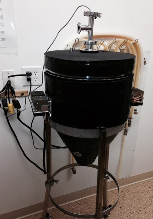
Step 9: For insulation, I used 3/4″ black foam type insulation. You can use anything as long as it has good insulation. Make sure you take the correct measurements of your conical before you begin cutting and make sure to leave space for the bottom dump valve.
Notes
To keep the fermenters from being connected at all times to the power supply on the wall, I used trailer wire harness plugs as indicated in the picture. I put the female ones on the power supply side and the male ones on the fermenter side to allow the power supply leads to be protected if the power supply is on and not connected to a fermenter. These were purchased at Lowes. To ensure quality connections in the Peltier cooler system, all wire splices should to soldered to ensure no heat is generated at the splice.


Share Post